Documentation
In this section I will explain how the model works, some core principals behind some of the settings as well as some tips for checking your model prior to commencing training. You can skim read this the first time through, but it's good to a get a basic idea of some of the principals coming up. I will refer (and link) back to this section several times when going over the settings.
The model itself is split into several sections (sub-models), all of which are entirely configurable. A lot of these sub-models will be familiar to you if you have used Faceswap before, but Phaze-A does also introduce some features which are unique to the model.
In addition, Phaze-A gives you the possibility to structure the routing through these sub-models in various ways. In this way, several existing Faceswap models can actually be recreated in Phaze-A (more on this later), as well as opening up the possibility to create many more configurations. If you are not already familiar with the basic layout of the Faceswap Shared Autoencoder, then you should familiarize yourself with it now from the training guide.
An important concept to understand is that of "shared weights". When a sub-model has shared weights, it means that it is learning information about both of the faces being trained on. Weights which are not shared are only learning information about the face on that side. The reason this is important is that you will have some control over which weights are shared and which weights are unique to each side.
The concept of shared weights is crucial to how Faceswap learns to swap faces. In the original Faceswap model, the model is structured:
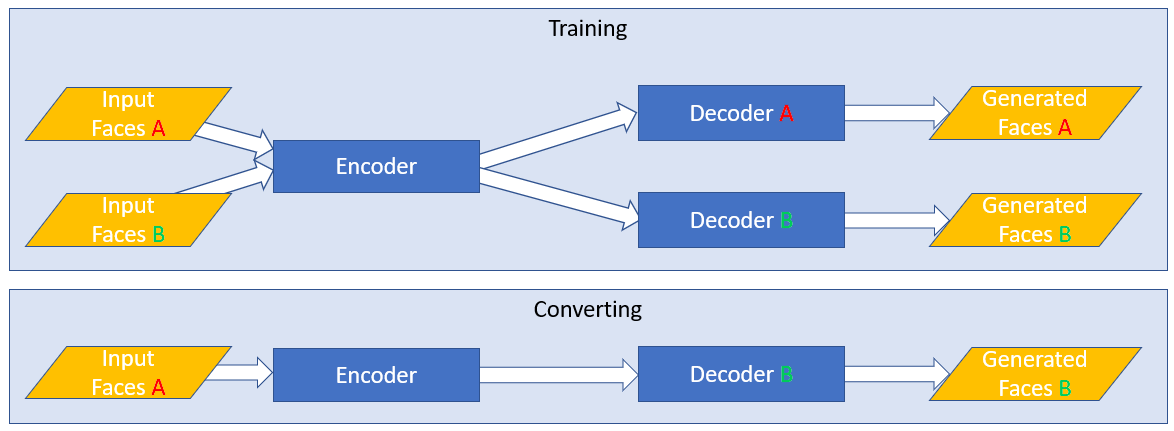
The encoder has shared weights. This means that the model is learning how to encode both of the faces in a single model. The encoder will be very good at encoding information for your two candidates.
The decoder is not shared. There are 2 separate Decoder models, each with their own weights. That means each decoder will receive an output from the encoder, and learn how to recreate the specific face. You will end up with 2 decoders, each one very good at taking the shared output of the encoder and turning it into the face for it's side.
The encoder in Phaze-A will always be shared, you will have no control over that as it is fundamental to how Faceswapping works, however you will have the possibility to insert more sub-models between the encoder and decoder(s) and will have control over which weights for these sub-models are shared and which are unique to each side.
Another effect of shared weights is that weights that are shared use less VRAM. A sub-model that has shared weights only needs to be created and stored in memory once. A sub-model that does not have shared weights needs to be created twice (once for each side), so requires double the space in GPU memory.
It is entirely possible to create a model in Phaze-A that is made up wholly of shared weights. This is not by deliberate design choice as I would suggest that doing this would be a bad idea, as it will do the exact opposite of what you want (it will be a good model at recreating either of your candidates, but it will never be able to swap them). Rather, it is a side-effect of opening up so many configuration options, that some will just not make sense to choose. This is just one example of why randomly selecting options is a poor idea.
Now we understand the concept of shared weights, let's talk about the sub-models that are available. As stated in the previous section, all sub-models (with the exception of the encoder) can be split or shared. I will go over each of the sub-models first and will then cover some layouts in the next section.
-
The Encoder
The encoder's job is to take an input image and to break it down into a vector that can be used to attempt to recreate the face. In layman's terms, it is looking at an image of a face, and trying to describe what it is seeing in as few words as possible. It is the distillation down of this information which allows us to perform the swap. We do not want to pass too much information through to the decoder, as otherwise the decoder will just learn to entirely recreate the image which the encoder is seeing (which means that a swap will not occur).
As an example, you would want the information "this person's eyes are looking right" to be passed through, as regardless of whether you are trying to recreate a face or swap a face, this information is important. You would not want the information "this person's eyes are blue" to be passed through, because you would want the color of the eyes to be correct for the face you are swapping.
With this in mind, you should be able to see that just throwing more parameters at the encoder is not the correct course of action. You are looking to tune your encoder to just the right level to pass through the right information to the decoders.
Phaze-A brings in a unique innovation to the choice of encoder. The traditional Faceswap encoder is not particularly complex, and has not really seen much development since the original model was released. By tapping into Keras API we have opened up access to a plethora of state of the art encoders. These encoders have nearly all been created with classification tasks in mind, however we can easily repurpose them for Faceswap. It is worth noting that the VRAM requirements can vary wildly between each encoder, so keep this in mind when trying to work out where to allocate your resources.
It is highly recommended you research the encoders if you want to learn more about them. They all have different methodologies and structures. Some will be better at some tasks than others. Do not assume that newer is necessarily better. The encoders were not developed with Faceswapping in mind, and have therefore not been tested within this context. Using these encoders should help to feedback into which kinds of architecture do and do not work for faceswapping, and will further feedback into developing more faceswapping specific encoders in future.
As well as the Keras API encoders, there is also a configurable Faceswap encoder, which can be used to create encoders from existing Faceswap models, or entirely new encoders altogether.
-
The Bottleneck
All Faceswapping models have a bottleneck, but it has generally been hidden from view from the user. The bottleneck serves a couple of purposes. It shrinks the encoder output down to try to get just the important information from the encoder. It also reduces the number of parameters going into the Fully Connected layers, which impact VRAM usage (more about that in the relevant settings section).
All existing Faceswap models use a Dense layer, usually with between 512 and 1024 nodes. Phaze-A allows you to configure this bottleneck and decide where to place it. It also allows you to use Pooling rather than a Dense layer for the bottleneck.
-
The Fully Connected Layers
This is where the "magic happens". In terms of concepts, this is the hardest one to explain. At the simplest level it is looking for patterns in the encoder output data, and trying to organize these patterns in a way that is helpful for the Decoders.
Again, all existing models have Fully Connected Layers. For models like Original and DFaker, these are within the shared encoder. For models like IAE and DFL-SAE (LIAE) these are the "inter" layers, and are split for each side of the model.
Phaze-A brings the ability to split (iae) or share (original) the fully connected layers, as well as give you full control over the number of layers and nodes to be used for each fully connected sub-model.
-
The Decoder
There isn't too much to say about the Decoder. All Faceswap models have a Decoder, be they split (like the original model) or shared (like the IAE model). The decoder's job is to take the compressed output from the encoder/fully connected layers and scale it back up to the required output, at which point the model's output will be compared to an original image for calculating loss.
Whilst the Decoder structure is mostly similar for all existing models, Phaze-A gives you some control over the structure and allocation of resources for the decoder
-
The G-Block
Outside of opening up routing and configuration options, the G-Block is the biggest innovation in Phaze-A. I should give special thanks to devloper/content creator Birbfakes who has done much experimentation around using this and helped inspire this particular implementation.
The G-Block is adapted from Nvidia's Style Gan, and has been adapted for Faceswapping purposes. In testing, using the G-Block in the way we have appears to help bring out better lighting and finer details (however, it can be quite subtle, so further research is always appreciated).
Because the number of parameters to set for Phaze-A has already hit fairly overwhelming levels, most of the parameters are locked down to close to stock implementation. I may open up some parameters in future, but for now you mostly have control over whether it is "on" or "off".
The G-Block is effectively split in to 2 sections:
The G-Block fully connected layers. This is a separate shared model that is automatically spawned if the G-Block is enabled, and receives the output from the Bottleneck as it's input. At stock settings this is a 3 deep Fully Connected model, with 512 nodes per layer, however this part is user configurable.
Decoder Pathway: Within the Decoder(s) another pathway is created to handle the output from the G-Block fully connected layers, and to combine this information back in with the standard encoder output, In the first instance, the output of the fully connected layers are put through another 3 Dense layers at 512 nodes each, with the output of this then passed through the G-Block itself (see Nvidia's paper).
None of the Decoder pathway parameters are configurable for the G-Block, although some control is afforded to the number of filters used for the block itself (more on this within model settings)
As mentioned previously, Phaze-A gives you many routing possibilities. Below are some illustrations of some of the layouts that you can configure. I will refer back to this section from the configuration settings for model architecture, but it is useful to get a visualization of some of the structural possibilities.
-
Existing Layouts
It is possible to create overall layouts for all existing modes in Faceswap (with the exception of unbalanced model). Below are the 3 main layouts currently in use in Faceswap.
The simplest layout is also the original layout. This has a shared encoder, shared fully connected layers then split decoders. This structure is used for the following existing Faceswap models: Dfaker, DFL-H128, DFL-SAE (DF), Original, Lightweight, Villain:
                                                                 ┌────────────────────┐
                                              ┌──────────────────►       Decoder      │
                                              │                  │          A         │
        ┌───────────────────┐       ┌─────────┴─────────┐        └────────────────────┘
        │                   │       │                   │
        │      Encoder      │       │  Fully Connected  │
        │      SHARED       ├───────►      SHARED       │
        │                   │       │                   │
        └───────────────────┘       └─────────┬─────────┘        ┌────────────────────┐
                                              │                  │       Decoder      │
                                              └──────────────────►          B         │
                                                                 └────────────────────┘
The next layout introduced was the Intermediate Autoencoder model. This consists of a shared encoder, 2 side fully connected layers + a shared fully connected layer, and then a shared decoder. This structure is used for the IAE Model:
                                    ┌────────────────────┐
                  ┌─────────────────►   Fully Connected  ├─────────────────┐
                  │                 │          A         │                 │
                  │                 └────────────────────┘                 │
        ┌─────────┴─────────┐                                    ┌─────────▼─────────┐
        │                   │       ┌────────────────────┐       │                   │
        │      Encoder      │       │   Fully Connected  │       │      Decoder      │
        │      SHARED       ├───────►       SHARED       ├───────►      SHARED       │
        │                   │       └────────────────────┘       │                   │
        └─────────┬─────────┘                                    └─────────▲─────────┘
                  │                 ┌────────────────────┐                 │
                  │                 │   Fully Connected  │                 │
                  └─────────────────►          B         ├─────────────────┘
                                    └────────────────────┘
DFL-SAE Introduced a model style (LIAE) which dispenses with the shared Fully Connected layer from the above IAE model, instead routing the "shared" fully connected through the A side's Fully Connected layers, effectively turning the A side's FC layers into a multi-purpose A-side/Shared model. This has the effect of saving VRAM, but at the expense of producing an unbalanced model (i.e. it will swap well A>B but not B>A):
                                    ┌────────────────────┐
                  ┌─────────────────►   Fully Connected  ├─────────────────┐
                  │                 │     A / SHARED     │                 │
                  │                 └────▲───────────┬───┘                 │
        ┌─────────┴─────────┐            │           │           ┌─────────▼─────────┐
        │                   │            │           │           │                   │
        │      Encoder      ├────────────┘           └───────────►      Decoder      │
        │      SHARED       │                                    │      SHARED       │
        │                   │                                    │                   │
        └─────────┬─────────┘                                    └─────────▲─────────┘
                  │                 ┌────────────────────┐                 │
                  │                 │   Fully Connected  │                 │
                  └─────────────────►          B         ├─────────────────┘
                                    └────────────────────┘
-
New Layouts
As well as the above, Phaze-A allows for new model layouts. Some routing configurations will make more sense than others. For example (as previously mentioned) if all the layers in the model are shared, then you will create a model which does a good job of recreating 2 identities, but never be able to swap them.
There are many different combinations that can be set, so rather than detail them all and fill the page with ascii flow charts, we will use one example.
If we wanted to create a model based around the original IAE model (shared encoder, split fc + shared, shared decoder), we might decide that we want to remove the shared fc layer, and replace it with the g-block, whilst also splitting the decoders. We would end up with a model structured like so:
                                    ┌────────────────────┐
                  ┌─────────────────►   Fully Connected  ├─────────────────┐
                  │                 │          A         │                 │
                  │                 └────────────────────┘       ┌─────────▼─────────┐
        ┌─────────┴─────────┐                                ┌───►      Decoder      │
        │                   │       ┌────────────────────┐   │   │         A         │
        │      Encoder      │       │     FC G-Block     ├───┘   └───────────────────┘
        │      SHARED       ├───────►       SHARED       ├───┐
        │                   │       └────────────────────┘   │   ┌───────────────────┐
        └─────────┬─────────┘                                │   │      Decoder      │
                  │                                          └───►         B         │
                  │                 ┌────────────────────┐       └─────────▲─────────┘
                  └─────────────────►   Fully Connected  │                 │
                                    │          B         ├─────────────────┘
                                    └────────────────────┘
This is just one example. We could keep the original shared fully connected layer in addition to the g-block, we could try routing shared FC data through the A side, we could keep the Decoders shared. There are many possibilities to experiment with, which will impact results and VRAM allocation.
With these routing options, as well as the ability to place the Bottleneck either at the end of the Shared Encoder or at the beginning of the Fully Connected Layers (be they split, shared or both), many different layouts can be created.
I do not plan to explain what Convolutional Filters are. There are plenty of resources on the internet for that, where you can do your own research. However, a concept you will need to familiarize yourself with is the "Filter Curve". I will refer back to this section at the relevant configuration options, but in the meantime you should understand what it is and why it exists.
There are several points, when creating your model, that you will want to recursively cycle through several layers, changing the number of parameters to be used at each recursion.
An example of this is the Decoder. In the simplest terms, the Decoder will receive an input that has a small dimensional space, but a large number of filters (e.g. 8x8x1024). As the dimensional space is increased on each recursion towards the target output size, the number of filters will need to be decreased until the target output size is achieved (e.g. 128x128.x3).
As the number of recursions required will vary from model to model, it is not possible to easily add parameters to explicitly set the number of filters for each upscale, with this in mind the concept of the "filter curve" is born, where you will be required to enter the minimum number of filters, the maximum number of filters, and the curve used to move through the recursions from this minimum to the maximum. Filters are always rounded down to the nearest 8.
The curve itself is expected to be a number between -1.0 and 1.0. Values below 0 will increase filters quicker at first and then slower. Numbers above 0 will increase filters slower at first then quicker. A value of 0 will linearly increase filters (i,e, the gap between each filter recursion will be identical).
As an example, if you have a Decoder which will upscale 4 times (from a decoder input of 8px to an output of 128px), there will be 4 recursions (8 > 16 > 32 > 64 > 128), and let's say you select a minimum number of filters as 64 and a maximum number of filters as 512 and you want to double the number of filters at each iteration, you would enter your settings as follows:
min_filters: 64
max_filters: 512
filter_curve: 0.45
This would give you the following filters: [512, 256, 128, 64]
Why 0.45 for the filter curve? Purely because that's how the math works out. I will include a link to a Google Sheet for assisting with calculating the curve at the end of this section, however, the number 0.45 only works for this number of recursions, A different number of recursions would require a different filter curve.
Using this example, we can see the impact that different curves have on the filter count at each recursion:
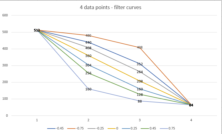
- curve1.png (41.33 KiB) Viewed 86213 times
As you can see a filter curve of 0 is linear (512 > 360 > 208 > 64). The gap between each recursion is exactly 152 (with the exception of the last filter due to rounding to nearest 8). The filter curve of 0.45 gives us the curve that we want (halving the number of filters at each step), whilst the 0.75 decreases quickly from 512 to 160 before decreasing slower to the target 64 min_filters. Looking at the other end, a filter of -0.75 decreases slowly from 512 to 480 before accelarating towards 64 min_filters.
As mentioned above, 0.45 is not a catch all solution for halving the number of filters at each step. It purely works in this situation, with our specified number of min/max filters and the number of upscales in the decoder. As an example, let's assume that we now have 6 upscalers in the decoder: (8 > 16 > 32 > 64 > 128 > 256 > 512), but we are going to use the same min/max filter settings of 64 and 512 respectively. Well, firstly, with these settings we can no longer halve the number of filters at each step, as we do not have enough recursions, so we need to find a filter curve we are happy with. The same filter curves but with the increased number of data points looks like the following:
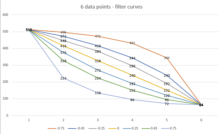
- curve2.png (48.12 KiB) Viewed 86213 times
It is worth noting that there may be some guesswork involved when you are first setting filters, however you can get feedback from the model structure to see if the layout is as you had hoped before committing to your settings. The next section covers this off.
A simple Google Sheet is provided here for quickly getting filter values for a given curve is here
With so many settings to configure, it is a good idea to check everything makes sense prior to actually launching into a training session. The training tab as an option to just display a summary of the model and exit, where you can look over the final structure.
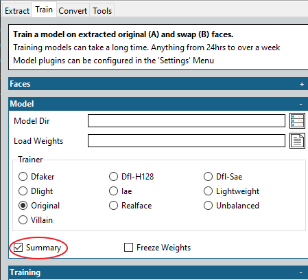
- summary.png (13.35 KiB) Viewed 86213 times
You do not need to provide input folders if you are generating a summary (although you do have to specify a model folder).
The output will give you a summary of the overall structure of the model, followed by a break-down of the structure of each individual sub-models. It is very useful for assessing whether you have structured things correctly, and whether you have got (for example) your filter curve adjusted as expected.
An example of the top-level summary can be seen here:
Code: Select all
__________________________________________________________________________________________________
Layer (type)                    Output Shape         Param #     Connected to
==================================================================================================
face_in_a (InputLayer)          [(None, 64, 64, 3)]  0
__________________________________________________________________________________________________
face_in_b (InputLayer)          [(None, 64, 64, 3)]  0
__________________________________________________________________________________________________
encoder (Functional)            (None, 512)          25603840    face_in_a[0][0]
                                                                 face_in_b[0][0]
__________________________________________________________________________________________________
fc_a (Functional)               (None, 16, 16, 1278) 71360964    encoder[0][0]
__________________________________________________________________________________________________
fc_gblock (Functional)          (None, 512)          787968      encoder[0][0]
                                                                 encoder[1][0]
__________________________________________________________________________________________________
fc_b (Functional)               (None, 16, 16, 1278) 71360964    encoder[1][0]
__________________________________________________________________________________________________
g_block_both (Functional)       (None, 16, 16, 1278) 36081216    fc_a[0][0]
                                                                 fc_gblock[0][0]
                                                                 fc_b[0][0]
                                                                 fc_gblock[1][0]
__________________________________________________________________________________________________
decoder_both (Functional)       [(None, 192, 192, 3) 56617012    g_block_both[0][0]
                                                                 g_block_both[1][0]
==================================================================================================
Total params: 261,811,964
Trainable params: 261,811,964
Non-trainable params: 0
At it's simplest level, the more parameters that the model contains, the more VRAM that the model will require. You can use this overview for helping you work out where you can balance VRAM allocation, as well as making sure that everything is structured as you'd expect.
Ok, now that your brain is completely fried from high-level Machine Learning concepts, lets look to apply these to the actual model settings.
I will go through the configuration options, and explain (as best I can) what they are and the impact they may have (if we know).
- To edit the model settings, GUI Users should select the
Settings menu and then select the Configure Settings... item. Alternatively you can click theConfigure Train Settings` button in the toolbar:
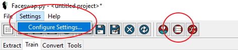
- settings1.png (14.58 KiB) Viewed 86213 times
- Once the Configuration menu has popped up, expand the
Model node underneath the Train node and select Phaze-A:
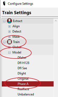
- settings2.png (14.13 KiB) Viewed 86213 times
- Cli users can access the settings by going to
faceswap/config/train.ini
The General settings are where we control the overall Model Architecture as well as the final output size of our model:
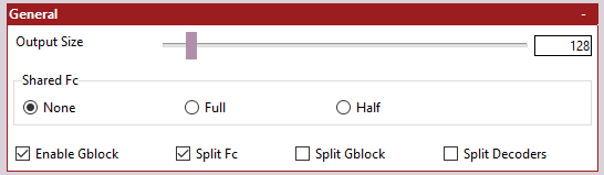
- settings_general.png (3.95 KiB) Viewed 86213 times
-
Output Size - The size of the final output image from the model. This should be divisible by 16. Selecting an output size of 128 will generate faces at 128 x 128px.
Be warned that increasing the output size will significantly increase the amount of VRAM required to train the model as well as significantly increase the amount of training time. Generally this will be an exponential increase (2x resolution will requre 4x the amount of VRAM and time).
It is also worth noting that "resolution" and "detail" are not the same thing. You may be looking to increase resolution in the hope of getting more detail, but for detail you will be looking to increase the complexity of other areas of the model (which will bring it's own VRAM and time implications).
If you are just starting out or are looking to experiment with other settings, then I would suggest keeping this value low, so that you can evaluate your changes without having to wait too long to train.
If you already have a target scene in mind, then you are going to need to make a judgement call over how much resolution you can get away with for your final scene, weighed against how much VRAM you have available, and where you want to be allocating that VRAM.
-
Shared FC - Whether to include a Shared Fully Connect Layer, and if so, the type of layer to use. Please refer to the The Model Architecture section for a more thorough break down of what impact these options will have on the overall model structure.
It is worth noting that if you enable the G-Block, then this will create it's own (uniquely configured) shared Fully Connected model. It may not be desirable to have a shared G-Block fully connected model and a shared standard fully connected model, although this has not been tested, so may be an area worthy of investigations. Either way, enabling both will definitely have VRAM implications.
Select from:
-
None - Do not include a shared Fully Connected model. This option will just create 2 Fully Connected models (1 for side A and 1 for side B), but will not create a shared instance for learning both sides.
-
Full - This will create a full Fully Connected model for learning shared data between both sets of faces. The model structure will be the same as is configured in the Hidden Layers section.
-
Half - This will re-use the 'A' side's Fully Connected model for learning shared data between both sets of faces. The model structure will be the same as is configured in the Hidden Layers. This option helps save VRAM by re-purposing the model for the A side as a "shared" model also. This helps save VRAM vs the Full option, but leads to an unbalanced model (will swap well from A>B but not well from B>A). It may also introduce identity bleed.
-
Architecture Options - The remaining options control the overall model architecture. You should refer back to the The Model Architecture section for a more thorough break down of what impact each of these options will have on the overall model structure.
-
Enable G-Block - Whether to enable the G-Block model. In testing, enabling the g-block helps to improve model detail and also lighting transfer.
If this option is enabled, it will create a G-Block shared hidden layers model (configurable in G-Block Hidden Layers Settings) for processing shared data between each side of the model. A further model is then created prior to the Decoder(s) to process this shared information. Configuration options are not currently exposed for this latter part of the G-Block, however you do have control over whether this data should be shared or split for each side.
As stated above it may not be desirable to enable both the G-Block and a Shared FC, but this has not been tested.
-
Split FC - Whether each side should get their own Fully Connected model, or whether the Fully Connected model should be shared for both sides.
Generally speaking, if this option is enabled, then the Decoders should definitely be split. It also would probably not make sense to enable the Shared Fc option if you are not splitting the Fully Connected models, as you would just end up with 2 identical shared models doing exactly the same thing.
-
Split Gblock - By default, the data that is fed into the G-Block is shared between the A and B side. It is possible, however, to split this for separate models for the A and B side.
It should be noted that, as previously stated, the G-Block is split into 2 sections. The shared G-Block Fully Connected model, which feeds the G-Block, and the G-Block itself. The shared G-Block Fully Connected model will always be shared between the A and B sides. Enabling this option splits the processing of this shared data to each side.
-
Split Decoders - Whether to create 2 separate decoders (one for each side), or to share a single decoder for both sides.
If the Fully Connected layers have not been split, then the Decoders should definitely be split, as otherwise the model will not learn how to swap. If the Fully Connected layers have been split, then it is up to you whether you keep a single combined decoder, or split a separate decoder for each side. An area worthy of experiment.
As stated in the Model Architecture settings, Phaze-A introduces a unique feature, allowing you to select a pre-existing encoder for use in Faceswap.
This section does not let you configure individual settings for the selected Encoder (these are available later), rather it lets you select, at a top level, which encoder to use and how it should be scaled.
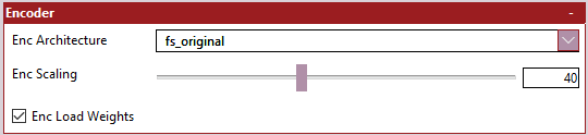
- settings_encoder.png (2.96 KiB) Viewed 86204 times
-
Enc Architecture - Select which encoder you wish to use.
You are strongly encouraged to do your own research around each of the Encoders, as this guide will not cover any of them. The tooltip for the Enc Architecture option will give you information about where each Encoder comes from, as well as a link to the academic paper. As well as selecting a pre-existing Encoder, you can also select the configurable 'fs_original' encoder.
-
Enc Scaling - How much to scale the encoder input by.
Many of these encoders were created with large input sizes, larger than is necessarily required for Faceswapping. As stated earlier, the encoder's job is to collate just enough information for the decoders to be able to reconstruct a face. We do not want too little information being collected, but similarly we do not want too much information collected. Maxing this setting out is nearly always the wrong thing to do.
The tooltip for Enc Architecture will tell you the input sizes expected by each encoder. This option allows you to shrink the input size to the encoder, in order to save VRAM for use elsewhere. Taking Densenet as an example, the maximum input size is 224px. If we actually want to feed the image in at 128px we would set encoder scaling to 0.575 (224 * 0.575 = 128). This scaling does not need to be set with 100% accuracy, as all input sizes are rounded down to the nearest size divisible by 16 pixels.
The ultimate impact of shrinking the Encoder scaling will be to reduce the number of parameters being fed to your bottleneck. This is generally a useful thing to do as fewer parameters = lower VRAM requirements. As stated in Checking Your Model you can use the model summary to ensure that you have set your input size correctly, and the corresponding size that is being fed into your bottleneck.
-
Enc Load Weights - Whether to load ImageNet weights for the encoder.
All the Keras based encoders (i.e. all of the encoders with the exception of fs_original) have the ability to load pre-trained weights that have been trained on ImageNet data. Whilst this is not as good as having weights that have been trained on Face data, it is still useful to us and can give us a jump start on training a new model.
Enabling this option will load ImageNet weights in when starting a new model. It is usually a good idea to freeze the Keras Encoder (covered in a later section) until the rest of the model catches up, as failure to do so will mean that these pre-trained weights will end up getting polluted by the randomly initialized weights in the other parts of the model, which will significantly erode any benefits you will have received.
Once the rest of the model has started catching up, you should unfreeze the Keras Encoder weights so that the encoder can continue to learn on the data that we are feeding it.
As stated earlier, the bottleneck serves to constrain the output from the Encoder prior to feeding the Fully Connected layers and, ultimately, the Decoder. You have several controls available to you for manipulating the bottleneck.
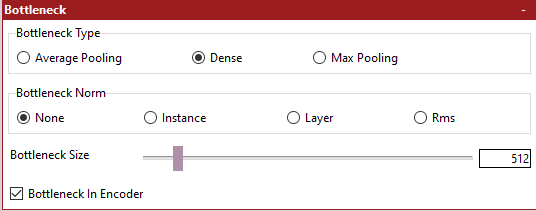
- settings_bottleneck.png (5.84 KiB) Viewed 86191 times
-
Bottleneck Type - The type of layer to use for the Bottleneck.
Traditionally Faceswap has used a Dense Layer as the Bottleneck, however many Autoencoder architectures outside of Faceswap choose to forego a Dense layer instead using a pooling layer. You should do your own research over which type of bottleneck you would like to use, as research into the effects of different bottlenecks for our purposes are limited at best.
-
Dense - At the most basic level, a Dense layer is given a certain number of "nodes". Each of these nodes is connected to every output from the previous layer. This can stack up parameters fast. As an example, if you have an output from the encoder in the shape 4, 4, 1024 (that is a dimensional space of 4 pixels, with a depth of 1024 layers), this layer would be flattend to 4 x 4 x 1024 = 16,384 outputs. These 16,384 outputs would then be connected to every node in the Dense layer. If you had set the Dense nodes to 512 then this would be 16,384 x 512 = 8,388,608 parameters.
-
Global Pooling - This covers both Max Pooling and Average Pooling, as they effectively do the same thing, but just use different methods for pooling data. Pooling is entirely dictated by the depth of the encoder output. Using the example above, if the encoder output shape is 4 x 4 x 1024 then the depth is 1024 (i.e. the last number in the encoder output shape). Data will be pooled to a shape of 1 x 1 x 1024 (pooling always reduces spatial dimensions to 1 pixel). This means that for every 4 pixels, the data will either be averaged (average pooling) or the maximum value taken (max pooling) to create this output.
It is also worth illustrating how the size of the bottleneck can impact the model when feeding into the following Fully Connected layers. Using the above example of an encoder output of 4 x 4 x 1024, lets assume that we have set our following Fully Connected layers to have a shape of 8 x 8 x 1280. This would mean that the output from the encoder has 16,384 outputs and the input to the Fully Connect Layers would have 8 x 8 x 1280 = 81,920 inputs.
If the output from the encoder was connected directly to the Fully Connected Layers we would be looking at creating 16,384 x 81,920 = 1,342,177,280 parameters. This is a pretty massive number. If we have a Dense Bottleneck of (say) 512 nodes, the number of parameters would be (16,384 * 512) + (512 * 81,920) = 50,331,648. Again, still a big number, but this is orders of magnitude (23 times, to be precise) smaller than implementing a direct connection between the encoder and the fully connected layers.
Ultimately the bottleneck is important as it helps constrain the encoder output, but it also helps to signifcantly reduce VRAM usage, to the point that without it, it would often be impossible to create a model that fits into available VRAM.
-
Bottleneck Norm - The type of normalization layer to use prior to feeding the bottleneck.
This is similar to Dense Norm in DFL. Select whether you wish to normalize the data prior to feeding the bottleneck or not, and if so, which type of normaliztion you would like to use.
-
Bottleneck Size - The number of nodes to include in the Dense layer
This option is only used if Dense has been selected for Bottleneck Type. See the information in Bottleneck Type for what impact this number has and how to choose it.
-
Bottleneck In Encoder - Whether to position the Bottleneck in the Encoder or not.
Traditionally, the bottleneck has been placed in the Encoder. As the encoder is always shared between both the A and B sides, this ensures that the bottleneck is also shared between both the A and B sides. Some later models have experimented with splitting fully connected layers for each side, and placing the bottleneck within these fully connected layers. This means that there will be multiple bottlenecks (depending on the final model structure, this could be a bottleneck for each of side A, side B, Combined and G-Block). This may or may not be desirable.
As previously discussed, the hidden layers are possibly the hardest part of the model to explain in simple terms. Ultimately, hidden layers work by connecting every single output from a previous layer to every single node of each fully connected layer to look for patterns in the data.
Not much research has been done on different hidden layer architecture in terms of Faceswap, so Phaze-A opens up options for controlling the depth and width of your hidden layers. Traditionally Faceswap has only ever had 1 fully connected layer. More than this has not been tested, but the availabilty is there to see what impact this might have on the swap.
It is important to understand that a Dense layer is 'flat'. This means that rather than having a width x height x depth shape (like the encoder/decoder input and output shapes) it has a 1 dimensional shape just consisting of nodes. The parameter structure in Phaze-A is still laid out in w x h x d format though, to make it easier to transition from the shape of the encoder output, to the shape of the decoder input. It also ensures that we maintain 'sane' parameters which can be reshaped into something which the decoder can work with, and so you don't need to reach for your calculator every time you need to set a parameter.
As an example, you may select a single fully connected layer with Fc Dimensions = 8 and Fc Max Filters = 1024. This translates to a decoder input shape of 8 x 8 x 1024. In reality, the hidden layer extrapolates these dimensions into a 1D layer of 8 x 8 x 1024 = 65,536 nodes.
- Image hidden.png (6.39 KiB) Viewed 86185 times
It is worth noting that if you have selected to use the G-Block, then the number of filters used for the G-Block will be dictated by the output shape of the hidden layers. The reason being that it helps maintain a consistent shape across the model, whilst also helping us to limit the number of parameters to be exposed.
If you have included upsamplers within the fully connected layers, and have not used "Upsampling2D" as your upsampler, then the number of filters used for the G-Block will be the same as the value given for fc_upsample_filters. In all other situations, the number of filters used for the G-Block will be the same as the value given for fc_max_filters.
-
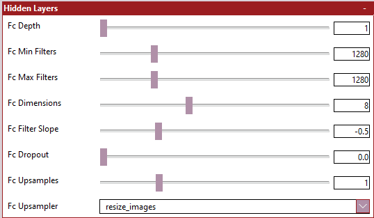
Fc Depth - The number of Hidden Layers to include within the model
Traditionally, Faceswap models have only ever had 1 fully connected layer, however you can include more. You will need to keep track of the number of connections you are creating between each hidden layer, as parameters can blow up quickly. Re-read the information in the Bottleneck configuration section to understand how parameters and connections can stack up.
-
Fc Min Filters - The minimum number of filters to use for Hidden Layers
If you only have 1 hidden layer, then this option will be ignored. If you have elected to have multiple hidden layers, then this is the number of filters for the 1st fully connected layer. The actual number of nodes within the first layer will be the figure given here multiplied by the value given for Fc Dimensions twice. For example, a filter value of 64 and Fc Dimension of 8 would give you 64 x 8 x 8 = 4096 nodes
-
Fc Max Filters - The maximum number of filters to use for Hidden Layers
This is the number of filters for the final fully connected layer (or the only fully connected layer if you have selected a Depth of 1. The actual number of nodes within this final layer will be the figure given here multiplied by the value given for Fc Dimensions twice. For example, a filter value of 1280 and Fc Dimension of 8 would give you 1280 x 8 x 8 = 81,920 nodes
-
Fc Dimensions - The dimensional space for the Hidden Layers output
The dimensions act as a scaling factor for the number of filters you provide. As previously stated, the actual number of nodes is this number squared multiplied by the number of filters that you elected to use. Setting the dimensions here dictates the final shape coming out of the Hidden Layers prior to feeding into the Decoder.
One thing to bear in mind... It is good practice to ensure that the number of dimensions are scaled to your selected output size. This is not entirely necessary, as the Decoders have a mechanism built in to re-scale the filters and dimensions to your chosen output size, but this may not always have the desired effect. Basically, the final output size from the Hidden Layers will be recursively doubled in size until the target resolution is reached.
For example, if you have selected a final output size of 192px, then 8 would not be a good choice for Dimension size as you cannot reach 192 by recursively doubling 8 (i.e. 8 x 2 = 16 x 2 = 32 x 2 = 64 x 2 = 128 x 2 = 256). A value of 6 would be a better choice for this output size: 6 x 2 = 12 x 2 = 24 x 2 = 48 x 2 = 96 x 2 = 192
Unfortunately that is not the only limitation. By reducing the dimensional space from 8 to 6 to hit your target output size, you actually massively reduce the number of nodes in the fully connected layer. For example, if you selected 1280 as the number of filters with, a dimension of 8 this would be 8 x 8 x 1280 = 81,920 nodes. However for a dimension of 6 this would be 6 x 6 x 1280 = 46,080 nodes. This is almost halve the number of nodes and therefore half the complexity. The logical thing here would be to increase the number of filters for the 192px output to something like 2304 (6 x 6 x 2304 = 82,944 nodes), however this will have a knock on effect of increasing the number of filters used in the G-Block (if selected) which is likely to bring it's own VRAM implications.
Ultimately, using output resolutions that are not a factor of 64 can lead to complications. It may be best to not think about the scaling and let the Decoders automatically handle this for you, but it has not been thoroughly tested. If you do decide to let the decoders handle this, then the number of filters may be scaled down slightly to ensure that the final output resolution is achieved. This method will ensure that the number of G-Block filters remains sane, whilst also keeping the number of nodes used in the hidden layers (regardless of output size) fairly similar.
As an example of how the auto-scaling works... if you select an output resolution of 192px, an FC Dimension of 8 and FC Max Filters of 1280, this will give you a total number of nodes as 81,920. This number of nodes cannot be scaled to an output size of 192px, so the number of filters will automatically be scaled down to 1278 giving a total number of nodes of 81,792 and an output shape that can be scaled up to the requested output resolution.
-
Fc Filter Slope - The slope to use to move from minimum filters to maximum filters
If there is more than 1 hidden layer selected then this sets the curve for moving from Fc Min Filters to Fc Max Filters. See the section Understanding The Filter Curve to get a thorough breakdown of how to set this value.
-
Fc Dropout - The Dropout Rate to use prior to each Hidden Layer
Dropout is a kind of regularization to prevent overfitting the model, and also to help keep deep-lying neurons alive. Dropout can be adjusted for existing models. I.e. you can start a model with a dropout value of 0.5 then lower it over time down to 0.0 by stopping the model, adjusting this parameter and restarting your model.
-
Fc Upsampler - The type of upsampler to use to scale up the final Hidden Layer output
The type of Upsampler to use. Often this will be the same as the Decoder Upscaler, but you may also want to use a different (perhaps more lightweight) upsampler at this stage, The tooltips give a fairly thorough explanation of each of the upsampling methods, so I will not repeat the information here.
-
Fc Upsamples - The number of times to scale up the final Hidden Layer output
More often than not, an upsample is included at the end of the Fully Connected layers, prior to feeding the decoder. This essentially doubles the dimensional space from your chosen Fc Dimension for each upsample that you create. For example, for Fc Dimension = 8 and FC Upsamples = 1 the output from the Fully Connected layers would be 16 x 16 in dimensional space.
-
Fc Upsample Filters - The number of filters to use for the upsamplers within the hidden layers
If you are using any upsampler other than Upsampling2D (which does not accept filters), then this is the number of filters to use for each upsampler contained within the fully connected layers. Bear in mind that if you are using repeated upsamples you can can very quickly stack up VRAM usage, if using a more complex upsampler.
If you have chosen to not enable the G-Block, then this section can be skipped.
As explained in the G-Block Overview the G-Block is split into 2 parts. The shared data that is used to feed the block, and the G-Block itself. The settings here allow us to configure the former (i.e. the shared data that is used to feed the block).
The structure of these settings are very similar to those of the Hidden Layer Settings, but are slightly less complicated as we are not constrained by keeping the data scaled for the output size, which means that we can work with the number of nodes directly, rather than an abstracted concept of filter size.
The default implementation has a depth of 3 to 6 with 512 nodes for each of these layers (i.e. min_filters = 512, max_filters = 512).
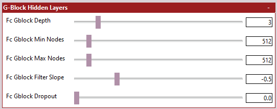
- settings_gblock_hidden.png (5.28 KiB) Viewed 86166 times
-
Fc Gblock Depth - The number of Hidden Layers to include within the model to feed the G-Block
The reference implementation contains 3 to 6 hidden layers to feed the G-Block. Here you can configure how many you would like in this section of the model. You will need to keep track of the number of connections you are creating between each hidden layer, as parameters can blow up quickly. Re-read the information in the Bottleneck configuration section to understand how parameters and connections can stack up.
-
Fc Gblock Min Nodes - The number of nodes to include within the first hidden layer
If you only have 1 hidden layer, then this option will be ignored. If you have elected to have multiple hidden layers, then this is the number of filters for the 1st fully connected layer.
-
Fc Gblock Max Nodes - The number of nodes to include within the final hidden layer
-
Fc Gblock Filter Slope - The number of nodes to include within the final hidden layer
If there is more than 1 hidden layer selected then this sets the curve for moving from Fc Gblock Min Filters to Fc Gblock Max Filters. See the section Understanding The Filter Curve to get a thorough breakdown of how to set this value. NB: If the minimum and maximum number of filters are identical, then the curve will have no effect (all layers will have the same number of nodes)
-
Fc Gblock Dropout - The number of nodes to include within the final hidden layer
Dropout is a kind of regularization to prevent overfitting the model, and also to help keep deep-lying neurons alive. Dropout can be adjusted for existing models. I.e. you can start a model with a dropout value of 0.5 then lower it over time down to 0.0 by stopping the model, adjusting this parameter and restarting your model.
The Decoder(s) now do the job of taking everything we've done with the input encoding and try to piece this together to make a face. The easiest (and simplified) way to think about the Decoder is that it takes a very small image (the encoder output) and upscales it until the target resolution is reached.
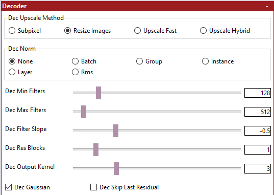
- settings_decoder.png (10.12 KiB) Viewed 86164 times
It is actually a little more complicated than this... A standard RGB image is defined in the shape (height, width, depth). So for a 128px image the shape would be 128, 128, 3. That is 128 pixels high, 128 pixels wide. The 'depth' category for an RGB image is the 3 channels of color information (red, green, blue).
What if we were to not store color information in the last dimension though? How about if we were to store other descriptive information about the image instead? This is, effectively, what our Neural Net does. We receive information from the encoder that may be in the shape (for example) of 8, 8, 1024. What this means is that we are receiving an image that is 8 pixels high by 8 pixels wide, but instead of just 3 channels of color information, we have 1024 bits of "descriptive information" (or filters) for each of these 8 pixels. In this way, a Neural Network can shrink down the dimensional space being used, whilst increasing the Depth, to describe the information within this dimensional space.
The decoder increases the dimensional space with each "upscale" whilst decreasing the depth (i.e. the filters). It learns to use this space and depth information at each upscale to eventually recreate the final image. As the dimensional space is doubled on each upscale iteration, then the number of filters should be reduced. Apart from anything else, lots of filters (especially on larger images) leads to a very high VRAM requirement.
This can be quite a difficult concept to understand, so I will try to drill down into a bit more detail on the relavant parameters.
-
Dec Upscale Method - The method to use for de-convolving the output image
There are several methods for "upscaling" the encoder output at each iteration, each with their advantages and disadvantages. The tooltips/helptext gives more information about the benefits and drawbacks of each.
-
Dec Norm - The normalization method to use
Whether to use normalization within each upscaler or not, and if so, which normalization method to use.
-
Dec Min Filters - The number of filters to use for the final upscale layer.
As explained earlier, as the dimensional space is increased at each upsample iteration, the number of filters used on the image is reduced. The value here is the number of filters to apply to the final upscale layer. That is, the upscale that takes you to the final output resolution. As the dimensional space at this point is large, the number of filters should be smaller.
-
Dec Max Filters - The number of filters to use for the first upscale layer.
As explained earlier, as the dimensional space is increased at each upsample iteration, the number of filters used on the image is reduced. The value here is the number of filters to apply to the first upscale layer. That is, the upscale that takes you from the encoder output size to the next size up.. As the dimensional space at this point is small, the number of filters should be larger.
-
Dec Filter Slope - The speed of movement from the maximum number of filters to the minumum number of filters over each upscale.
You will need to refer to the section Understanding The Filter Curve to get a decent handle on how to set this. The section will also tell you how to calculate the number of "upscales" that will exist within your decoder. Ultimately, this lets you control the rate of change of filters between each upscale.
-
Dec Res Blocks - Whether to use Residual Blocks in the Decoder or not.
Residual blocks can help the model learn. Some existing models use them, some do not. You can do your own research about what a Residual block is meant to achieve.
-
Dec Output Kernel - The kernel size of the final Convolutional layer.
The final convolutional layer is responsible for turning the last upscaled layer into the RGB output image. The concept of kernel size is too complicated and in depth to cover in this guide, but all pre-existing Faceswap models use a kernel size of 5. Generally speaking, larger kernels need more VRAM than smaller kernels.
-
Dec Gaussian - Whether to apply Gaussian Noise to each upscale or not.
Gaussian Noise is a form of regularization. It attempts to keep nodes within the model alive, whilst also preventing overfitting. Traditionally Faceswap models have not used this type of regularization, so it is a new addition for Phaze-A. You can select whether to use Gaussian Noise here or not.
-
Dec Skip Last Residual - Whether to include a Residual Block within the final upscale layer.
Some models (e.g. Dfaker) choose not to have a Residual Block for the final upscale. Whether this is beneficial or not is still an open question, however you can elect to not have a Residual Block within the final upscale here. NB: If you have selected not to have Residual Blocks within your decoder, then this option will be ignored.
Phaze-A allows you to freeze and load weights from pretty much every sub-model. This can help shorten the start up time for new models, and also opens up some interesting opportunities for model re-use.
These settings will only be read if either Freeze Weights or Load Weights has been passed in has an option when launching Faceswap,

- settings_weights.png (6.59 KiB) Viewed 86162 times
The sub-models that each option relates to should be, for the most part, self-explanatory, however it is worth noting:
Keras Encoder just freezes the weights within a Keras-App model (it will not do anything if the fs_encoder has been selected), This is useful when loading the keras ImageNet weights as it ensures that the Bottleneck remains unfrozen. If you are not looking to load and freeze the Keras ImageNet weights, then you should probably select Encoder instead.
For sub-models that have been split or shared; if you have elected to have them split then you should be selecting the models which end with A or B. If you have chosen not to split them, then you should be selecting the model that ends with Both
Whilst all combinations of sub-models are available for selection, many will only make sense to select for certain architectures. For example, if you have not elected to have a shared hidden layer sub-model, then enabling fc_shared will have no effect here. Make sure that your selections make sense for the model architecture that you are using. Use the model summary if in doubt.
This section is only required if you have decided to use the fs_encoder as your Encoder. For any other encoders, this section will be ignored.
As stated earlier, the standard (and often used) Faceswap Encoder is fairly simple. As we have added so many other possible encoders, we have decided to keep configuration for the Faceswap encoder fairly simple too.
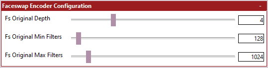
- settings_fs_encoder.png (3.82 KiB) Viewed 86151 times
It is worth noting that the Encoder does not use a filter curve, and has been massively simplified. When you select a minimum filters value, this value will be used for the first downscaler. For each subsequent downscaler, the number of filters used will be doubled until the maximum value is reached. For example, for an encoder depth of 4 and a minimum filters value of 64, the number of filters used will be 64 -> 128 -> 256 -> 512 at each downscale.
-
FS Original Depth - The Depth of the Encoder.
The depth is basically how many "downscalers" are included within the Faceswap Encoder. The Encoder effectively does the opposite of what the Decoder does. It takes an input image of a certain size (dictated by the enc_scaling parameter) and shrinks the image, spatially, whilst expanding the depth of each image (i.e. at each iteration, the image is a smaller size, but it contains more information describing what is within this smaller image).
You will want to set this figure based on the desired spatial output from your encoder, calculated from the input size you have selected. For example, if you have an input size of 64px (64, 64, 3) and you are targeting an encoder output size of 4, 4, 1024 (that is an image which is 4 pixels wide and high, with a depth of 1024) you would want to specify a depth of 4. As each downscale halves the spatial dimension of the image a depth of 4 would give you 64 -> 32 -> 16 -> 8 -> 4, reaching your target output of size of 4px.
-
FS Original Min Filters - The number of filters to allocate to the first downscaler.
As explained in the Decoder settings, as the spatial dimensions of the image decreases, through each downscale, the number of filters should increase (to collect more valuable information). The value given here is the number of filters to use for the first downscaler. The number of flters used for subsequent downscalers will be doubled each time until the maximum number of filters specified is reached, or we complete the iteration cycle.
-
FS Original Max Filters - The number of filters to allocate to the final downscaler.
This is a hard cap on the number of filters to use. As stated earlier, the number of filters used for each downscaler is double the previous layer's. If the number of filters hits the cap set here, then filters will stop increasing once the cap is reached.
This section is only required if you have decided to use mobilenet as your Encoder. For any other encoders, this section will be ignored.
MobileNet opens up some additional configuration options that can be set here. You are advised to research MobileNet to get a better idea of what impact these parameters will have.
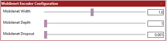
- settings_mobilenet_encoder.png (3.56 KiB) Viewed 86151 times
The tooltips/help text fairly extensively explain what these do, so I will not repeat that information. Do keep in mind that you have limited control over what is set here if you are planning to load ImageNet weights.
-
MobileNet Width - The width of the MobileNet Encoder.
-
MobileNet Depth - [v1 Only] - The depth of the MobileNet V1 Encoder.
-
MobileNet DropOut [v1 Only] - The dropout rate of the MobileNet V1 Encoder.


